Monday, March 26, 2012
Sunday, March 25, 2012
How to remove Nav bar of a Blog
- Login to Blogger.
- On the Blogger Dashboard, click on the Template link of the blog that you want to disable its NavBar. You can also click Customize on NavBar while visiting your blog.
- The Edit HTML page under Template tab should be loaded. Click on the drop down box beside Change the Blogger NavBar and select Off.
- Click on SAVE TEMPLATE CHANGES button when done.
- Sign in to Blogger.
- On the Blogger Dashboard, click on the Layout link of the blog that you want to disable its NavBar. You can also click Customize on NavBar while visiting your blog.
- Under the Layout tab, click on Edit HTML tab to view the template’s HTML code.
- Search for the following line of code:
]]>
Before the line, add in the following line of code:
#navbar { display: none; }
or:
#navbar-iframe { display: none !important; }
- Click on SAVE TEMPLATE to make the change effective.
- Login to Blogger.
- On the Blogger Dashboard, click on the Template link of the blog that you want to disable its NavBar. You can also click Customize on NavBar while visiting your blog.
- The Edit HTML page under Template tab should be loaded. If not, go to the tab.
- Search for the following line of code:
</style>
Then, add the following line of code before that line:
#navbar-iframe { display: none; }
The Blogger Classic Template uses iframe to load the NavBar, and styles it with ID named navbar-iframe. The name actually also works for new Blogger Widget Template too. - After hiding the Nav Bar in Blogger using Classic Template, there tends to be a gap that replaces the navigation bar. The gap may be white, red, green, blue, or black in color, depends on what is your background color. To remove the gap, find the following code (normally near the top of the HTML):
body {
Add in the following like of code after the body tag:
position: relative;

top: -32px;
- Click on SAVE TEMPLATE CHANGES button when done.
Saturday, March 24, 2012
Electronics Projects: Polarity Protection Circuit
There are many types of electronics equipment which is active by DC source. If we connect the DC source in the reverse direction i.e alter the negative positive side of the source then the electronics equipment can be damaged. To protect the electronics component we use the circuit because if the polarity is reversed then the alarm is active. Diode-IN4007
Circuit Diagram
Electronics Projects: Create a line mixer
Maximum time we need many input signal from one output. For example microphone. To perform this operation we can use the circuit(line mixer) because the cost of the circuit is so small. The circuit has 3 input signal and each input is controlled by each 10K variable resistor. The whole circuit is perform by one transistor.
Capacitor-5 Mfd/16V/2 Nos.,100 Mfd/16V/1 Nos.,
Transistor-BC-109/(NPN)1 Nos.,
Circuit Diagram
Requirements:
Resistor-10k/3 Nos., 22k/3 Nos., 2k2/1 Nos.,Capacitor-5 Mfd/16V/2 Nos.,100 Mfd/16V/1 Nos.,
Transistor-BC-109/(NPN)1 Nos.,
Electronics Circuit: Battery Discharge Monitor
Here is a battery monitor circuit which disconnects the load when the battery is discharged, preventing a deep discharge which could cause permanent battery damage. The battery is automatically reconnected when a battery charger or other DC source is connected across the load. Select a relay which requires less than 100ma coil current and with contacts capable of handling the load and charging currents.
Wednesday, March 21, 2012
Electronics projects: Create A Digital Clock
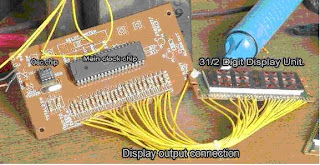
Now-a-days most of the Electronic Hobbyist & Professionals are like to make Microcontroller based Digital clock circuit, the photographs here is a non microcontroller based Electronic Digital Clock. this clock needs only 2 ICs. no programming or any other chips needed for this clock.
Circuit Diagram:
Main clock chip-MM5387
Osc chip-MM5369
Features:
- 50Hz or 60Hz operation.
- Single Power Supply.
- 12/24 Hours Display Format.
- AM/PM output.
- 12/24 hour format.
- 24 hour alarm setting.
- Fast & Slow set control.
- Power failure Indication.
- All counters resettable.
- Direct interface to LED Displays.
- 9 minute snooze alarm.
- Presettable 59 min. sleep timers.
Electronics projects: Voltage Regulator Circuit
This post is written about voltage regulator circuit. By the circuit we can adjust any voltage between 1V to 9V. In the circuit the voltage is adjusted by a regulator IC LM-317T. Pin-1 of the IC is input, Pin-2 is the adjust pin, Pin-3 is the output
Circuit Diagram
Requirements
Diode -1N4001x4,IC1-LM317T,capacitor:C1-2200 mfd/25V,C2-0.22 mfd/160V,C3-10 mfd/40V,C4-10 mfd/40V, switch:S1-1 pole 6 way Switch.Transformer-12 V, 1A Sec.
Subscribe to:
Comments (Atom)


