

Showing posts with label Electronics Projects. Show all posts
Showing posts with label Electronics Projects. Show all posts
Wednesday, June 6, 2012
Saturday, March 24, 2012
Electronics Projects: Voltage Doubler Circuit
By the circuit voltage is increased 2-times of input voltage which comes from transformers. It requires IN4007 diode.
Circuit Diagram

Electronics Projects: Voltage Quadrupler Circuit
By the circuit we can get 4-times of input voltage . if we supply 5v then we get 20V output voltage
Circuit Diagram

Electronics Projects: Polarity Protection Circuit
There are many types of electronics equipment which is active by DC source. If we connect the DC source in the reverse direction i.e alter the negative positive side of the source then the electronics equipment can be damaged. To protect the electronics component we use the circuit because if the polarity is reversed then the alarm is active. Diode-IN4007
Circuit Diagram

Electronics Projects: Auto Polarity Protection Circuit
The circuit is used to auto polarity protection. It can applied any circuit which is perform by battery. So lets see the circuit. The requirement of the circuit is Diode-IN4007
Circuit Diagram

Electronics Projects: Create a High Value Non Polar Capacitor
Now I will discuss about a topics i.e high value non polar capacitor . Several times we need high value non polar capacitor but it is rare in the market. So I will give you a circuit that can create high value non polar capacitor. It is created by only diode and capacitor.
Circuit Diagram

Electronics Projects: Create a line mixer
Maximum time we need many input signal from one output. For example microphone. To perform this operation we can use the circuit(line mixer) because the cost of the circuit is so small. The circuit has 3 input signal and each input is controlled by each 10K variable resistor. The whole circuit is perform by one transistor.

Capacitor-5 Mfd/16V/2 Nos.,100 Mfd/16V/1 Nos.,
Transistor-BC-109/(NPN)1 Nos.,
Circuit Diagram

Requirements:
Resistor-10k/3 Nos., 22k/3 Nos., 2k2/1 Nos.,Capacitor-5 Mfd/16V/2 Nos.,100 Mfd/16V/1 Nos.,
Transistor-BC-109/(NPN)1 Nos.,
Electronics Projects: Create a 9Volt Power supply
There are many times we need 9Volt power supply. By the circuit we can produce 9volt output. Please see the circuit diagram.

Requirements:
1.Input-(220-250)V.AC
2.Transformer-12-0-12volts
3.Diode-D1,D2-in4001,D3-BZY88,9.1v
4.Resistor-R1-390ohm
5.Capacitor-(C1-100/25),(C2-100/15)
6.Transistor-TIP41A
Audio Amplifiers for Small Speaker Applications

The figure shows a 4-transistor utility amplifier suitable for a variety of projects including receivers, intercoms, microphones, telephone pick-up coils, and general audio monitoring. Three cell battery packs giving about 4.5 volts are recommended
Electronics Circuit: Battery Discharge Monitor
Here is a battery monitor circuit which disconnects the load when the battery is discharged, preventing a deep discharge which could cause permanent battery damage. The battery is automatically reconnected when a battery charger or other DC source is connected across the load. Select a relay which requires less than 100ma coil current and with contacts capable of handling the load and charging currents.


Wednesday, March 21, 2012
Electronics Projects: A door bell circuit
To operate the circuit you need only 2.4-3.3V DC
Circuit Diagram:

Requirements:
1.8 ohm Loudspeaker
2.Bellpush
3. IC:HT-2811
4. Capacitor: 220k,3.3uf tant. 330k,4.7uf tant
5. Transistor:ZTX302,ZTX502
6. 3V DC source
7. Resistor: 680K
Electronics Projects: An excellent melody creator
We can create the circuit only by a IC UM-66. To operate the circuit you can use two pencil battery.

Electronics projects: Create A Digital Clock
Now-a-days most of the Electronic Hobbyist & Professionals are like to make Microcontroller based Digital clock circuit, the photographs here is a non microcontroller based Electronic Digital Clock. this clock needs only 2 ICs. no programming or any other chips needed for this clock.

Circuit Diagram:


Main clock chip-MM5387
Osc chip-MM5369
Features:
- 50Hz or 60Hz operation.
- Single Power Supply.
- 12/24 Hours Display Format.
- AM/PM output.
- 12/24 hour format.
- 24 hour alarm setting.
- Fast & Slow set control.
- Power failure Indication.
- All counters resettable.
- Direct interface to LED Displays.
- 9 minute snooze alarm.
- Presettable 59 min. sleep timers.
Electronics projects: Create a siren only using an IC
By the circuit we can create as like a siren. Power supply required only 3V DC.

Electronics projects: Voltage Regulator Circuit
This post is written about voltage regulator circuit. By the circuit we can adjust any voltage between 1V to 9V. In the circuit the voltage is adjusted by a regulator IC LM-317T. Pin-1 of the IC is input, Pin-2 is the adjust pin, Pin-3 is the output
Circuit Diagram

Requirements
Diode -1N4001x4,IC1-LM317T,capacitor:C1-2200 mfd/25V,C2-0.22 mfd/160V,C3-10 mfd/40V,C4-10 mfd/40V, switch:S1-1 pole 6 way Switch.Transformer-12 V, 1A Sec.Electronics projects: 12V DC to 120V AC converter
Today I will discuss about a converter, with the help of the circuit we can easily convert 12v DC to 120v AC. So lets go to the circuit diagram
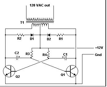
Requirements
- capacitor: C1, C2 - 68 μf, 25 V Tantalum Capacitor
- Resistor: R1, R2 - 10 Ohm, 5 Watt , R3, R4 - 180 Ohm, 1 Watt
- Diode: D1, D2 - HEP 154 Silicon Diode
- Transistor: Q1, Q2 - 2N3055 NPN Transistor
- Transformer: T1 - 24V, Center Tapped Transformer
- Others: Connecting Wire
Above circuit is called inverter and we can easily create it
Subscribe to:
Posts (Atom)